miniMO is a reprogrammable synthesizer module designed to encourage everyone to try modular synthesis. Currently there are two models available: one is PCB-based with soldered components, whilst the other (code name Noisette) is built on 3D-printed parts and requires no soldering. I will show you how to assemble and program the latter model.
This guide assumes you have a basic knowledge of electronics, and access to a multimeter, a 3D printer, and an Arduino (or ISP).
Schematic of the PCB version – same circuit except for the power switch and a different value for the LED resistor.
Note: I print the breadboard with a small (0.25) nozzle; I have heard of people who print small features with 0.4 nozzles, but I haven’t figured out how. Also, I take the breadboard clips from a commercial breadboard (I have searched everywhere for a clip supplier, to no avail).
Introducing Le Noisette
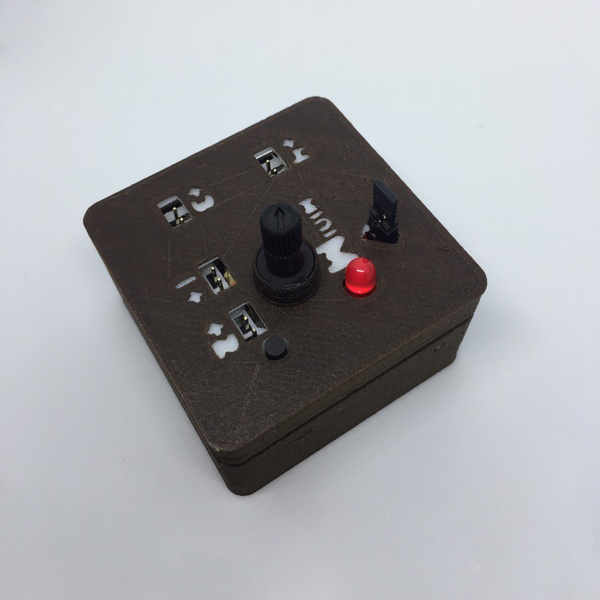
3DPrinted parts-based module, 5x5x4.5 cm in size, Code name Noisette -the synth you can print
The Noisette is the latest of a series of 3d printed miniMO models, and it is smaller, easier to assemble, and overall more reliable than its predecessors.
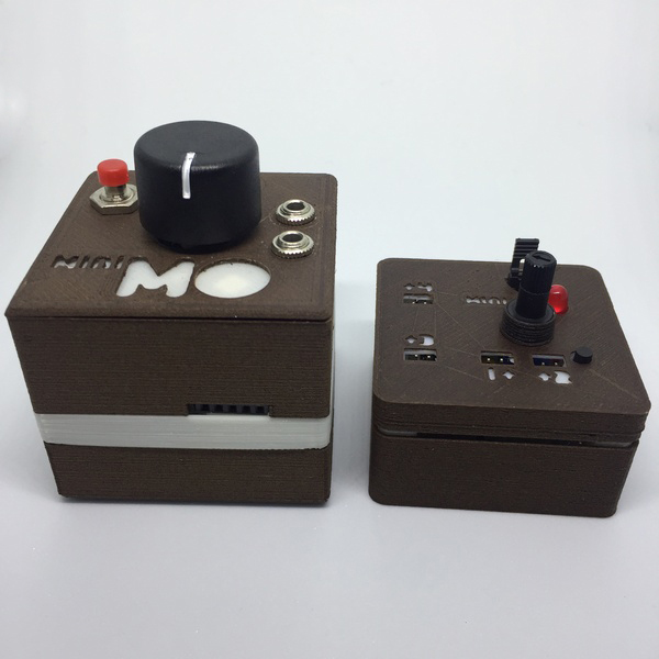
Previous iteration, “cafe latte”, to the left. The Noisette is about half the height but packs the same punch, hence the name
Every part that is not an electronic component is 3D printed, including a custom breadboard.

The Noisette features the same processor (ATtiny85), internals and ports as the PCB-based model, and it operates just like it, including programming from an Arduino. Unlike the PCB model, the Noisette doesn’t easily switch between internal and external power sources, but it runs on two (CR2032) batteries in parallel for extended operation time.

The PCB and 3D printed miniMO work perfectly well together
Build Overview
We’ll build the module from the bottom up. We’ll start with the battery compartment, then assemble the circuit on the breadboard, then place the board over the battery compartment and secure the electronic components. Finally we’ll add a case, which is entirely optional but cool nonetheless.
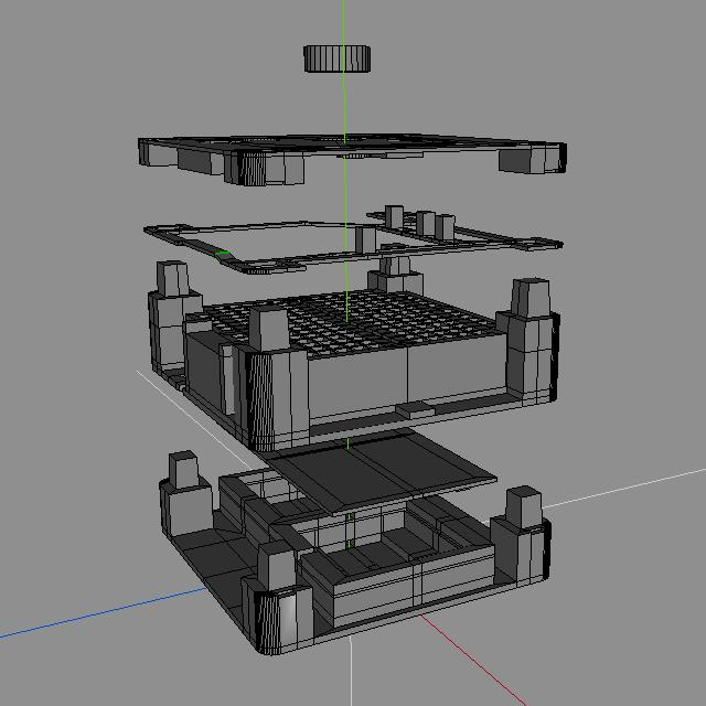
Made with Wings3D, the software of choice for designing KiCad parts, too
Wire color Conventions: red is positive, black is negative, yellow denotes an input signal, and blue an output signal.
Assembly
Battery Compartment
The battery compartment holds two CR2032 batteries in parallel. Here is the empty base:

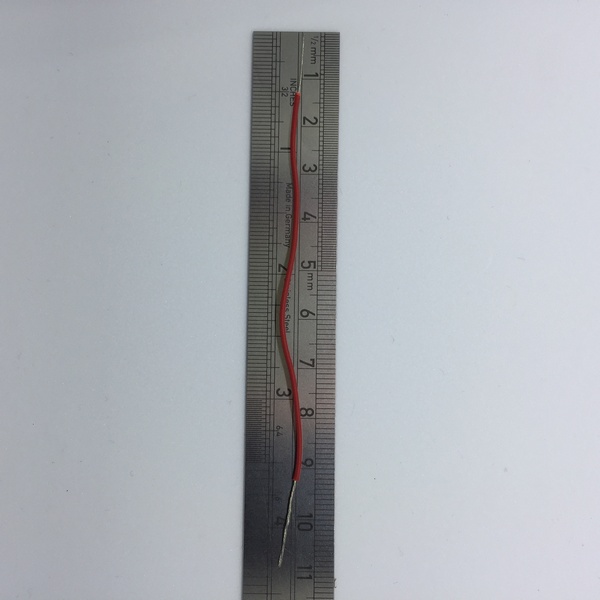
The first element we’ll place is a wire attached to a custom switch to turn the device on and off.
- Cut a length of stranded wire about 11cm long (4 and a half inches). Strip the ends and roll the exposed wire to keep it neat.
- Get a group of four header pins, and detach one. In the group of three, remove and discard the metallic shaft from one of the side pins.

- Turn the single pin around and insert it from underneath in the space left by the shaft you just removed.
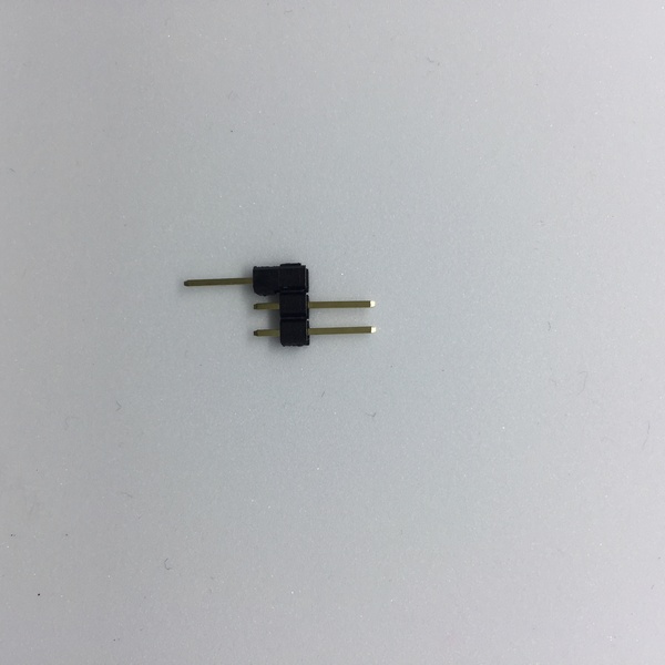
- Roll one of the exposed strands of wire around and between the long pins, then place the jumper on those same pins to secure the lot.

Finished “switch wire”
- Bring back the printed base. Now, cut a short length of (single core) wire, strip the ends and pass it under the division between compartments. Pass the loose end of the “switch wire” through the (lower) hole in one of the compartments, and roll or tie it against the exposed end of the single core wire. Both wires must touch the battery, so it’s a good idea to curl the edges of the single core wire up.

Sorry that I didn’t follow the color convention: that yellow wire should be red.
- Grab the batteries and place them in the compartments, + side down. Cut a short length of (single core) wire, strip and curl the ends, and place it so it fits snugly in the notch between compartments.

- Get the Multimeter and place one probe over the back of one battery, and the other between the short pins of the switch. It should read 3 volts; if you don’t get any readings, revise the wires and make sure they all touch the batteries.
- Cut and strip a length of single core wire about half the size of the switch wire. Get the battery compartment lid, and pass a short length of this wire through the “holder” in one of the sides. Bend the end to help it make contact with the battery.

- Place the lid on the battery compartment; it should snap into place. This last wire goes on the side opposite to the switch wire.

- Do a second check with the Multimeter, this time between the two exposed pins of the switch and the exposed wire opposite. If you read 3volts, congratulations! you’ve finished the battery holder. If you don’t, remove the lid and check that all the wires are touching the batteries.
Circuit Compartment
To build the breadboard, you will need two sets of joined clips for the side rails, and 30 individual clips for the terminal strips. They should fit fairly well in the printed part, but it is fine it they protrude a tiny bit (1mm).

I wish I could find a supplier for the clips
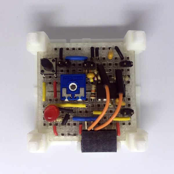
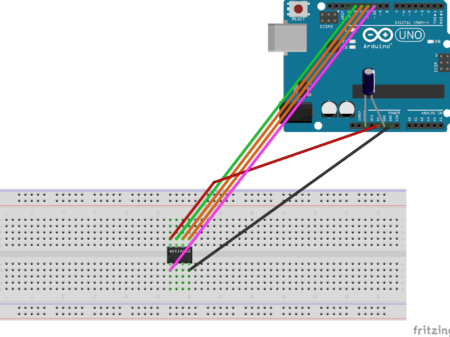
Let’s build the circuit! I’ve already linked the schematic, below you will see several pictures of the actual build, and here’s a diagram made with Fritzing: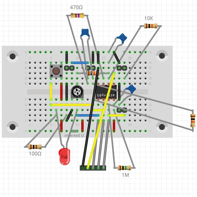 Yeah, I know what you’re thinking. Here’s another picture without the header:
 Doesn’t look much different but you should be able to tell what goes where. In any case, here’s a link to the fritzing file, so if push comes to shove, open it with the program and remove any elements that block your view.
- I assemble the circuit in this order: processor, jumper wires, resistors, capacitors, LED, “jittery things”.
- When you are about to place the 2-pin headers, use pliers (or your fingers) to slide the plastic bit so that the metal shafts are about the same length on both sides: you want them to “catch” a bit and mostly stay in place -don’t worry if they are still finicky.
- If you make the jumper wires yourself, make sure the ends are long enough to make good contact with the clips.
Some components missing for the sake of clarity
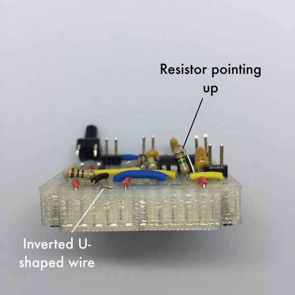
- The 1M resistor won’t fit horizontally. Bend one of the legs against the body and place it “standing up”.
- Don’t forget to place the exposed U-shaped wire in the positive rail!
- In order to place the LED you’ll have to bend the anode twice. I covered the “flat” bit with a short length of shrinking tube.

The female header used for programming fits in place over the board. You will need to attach two wires to it -here’s how:
- Get the m-m jumper wire and cut it in two parts. Shorten each part to about 4cm (1.5 inch), expose a bit of wire on the cut end, and bend it to make a little hook.
- Get the female header, use pliers to remove the two last metallic pieces from the back (4 and 5, counting from left to right), and flatten their ends.
- Latch the end of each wire to the U shape of a metallic piece. Don’t make extra bends or knots.

- Reassemble the metallic pieces into the female header. I use my fingers to press them a bit in place, then I press further with the pliers.

Finished part. You don’t need to cut the header’s original metallic ends, just bend them upwards a little bit so that they don’t get in the way of any other component.


- When you place the female header, the free wires go over the ATtiny and into their respective places. Bend their ends so that they rest as flat as possible against the board.

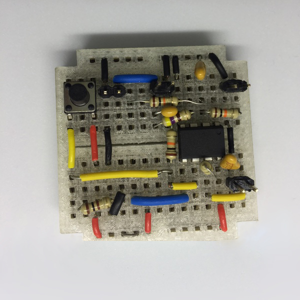
Here is the board with all the components in place.
- Get the board holder and place the board inside. In case of doubt, the female header rests against a raised column which is only in one side.

- Place the board holder over the battery holder.

- Pass the positive and negative wires through the slots in the base of the breadboard holder. Bend the negative wire and insert the end in any free space within the breadboard’s negative rail. Place the long pin of the positive “wire switch” in the free space of the positive rail, making sure that the short pins rest behind the exposed inverted “U”.
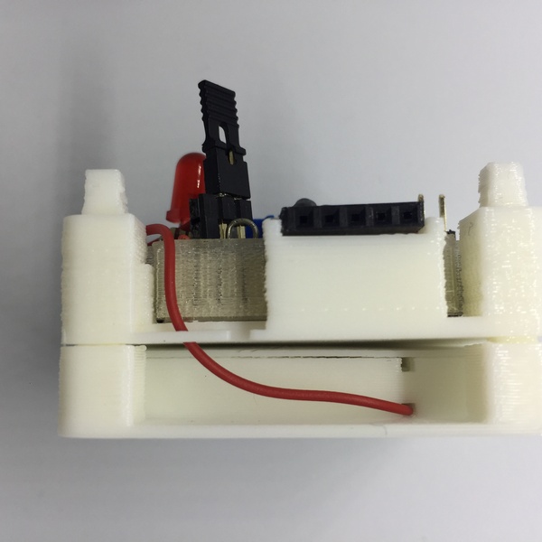
- The makeshift switch now pivots between two positions: free, and resting against the inverted “U”. In this position it closes the circuit, and that’s how you turn the module on.

One thing to take on account: when you turn your miniMO on for the first time, the LED won’t light up, because you haven’t programmed the chip yet. Let’s finish the assembly and later I’ll show you how to program it.
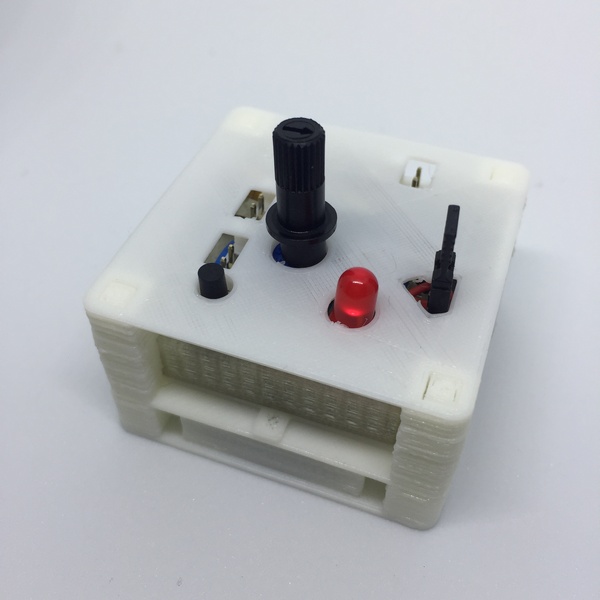
- By now I’m sure you’ll have noticed how several components don’t want to stay in place: that’s why I was calling them “jittery things”. To start putting a remedy to it, get the “ports holder” part and place it over the board. Pay special attention that there is a line passing between the pins of each and every header.
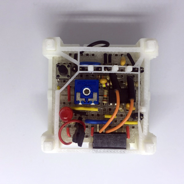
- To secure the switch and potentiometer in place, fit the printed part named “top” over the board holder, closing the module.
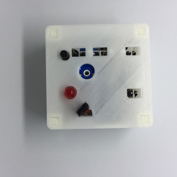
- Put the potentiometer shaft in place, take a well deserved break and return later to program the module.
Programming
Getting ready
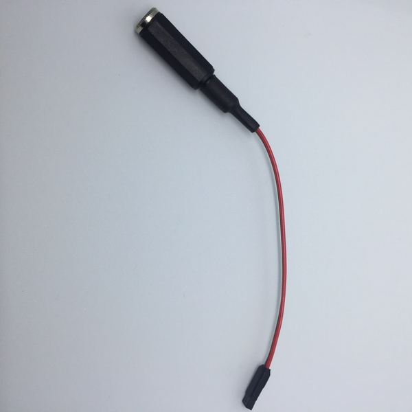
- Before you program miniMO, connect one of the ports closest to the knob to an amplifier; you need a custom cable to do this. In one end of this cable you will have a couple female headers, and in the other a connector of your choice; I make them with mini jacks.

I made two of these cables, one for output, one for input, and so far that’s all I’ve needed.
- I solder the cables I make, but a quick search for “3.5mm mini jack terminal block” shows several models for sale that don’t require any soldering.
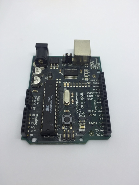
- You will also need an Arduino, programmed to be itself a programmer for miniMO
- Open the guide on how to program miniMO, and follow the steps up to “Connect miniMO to Arduino”. Don’t close the guide, as we’ll return to it once we’ve done connecting the module
- Finally, you’ll need 5 male-male jumper wires to connect the module to Arduino
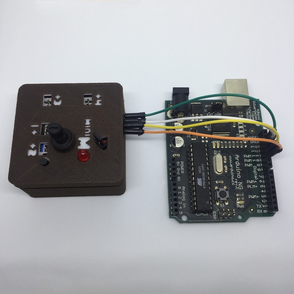
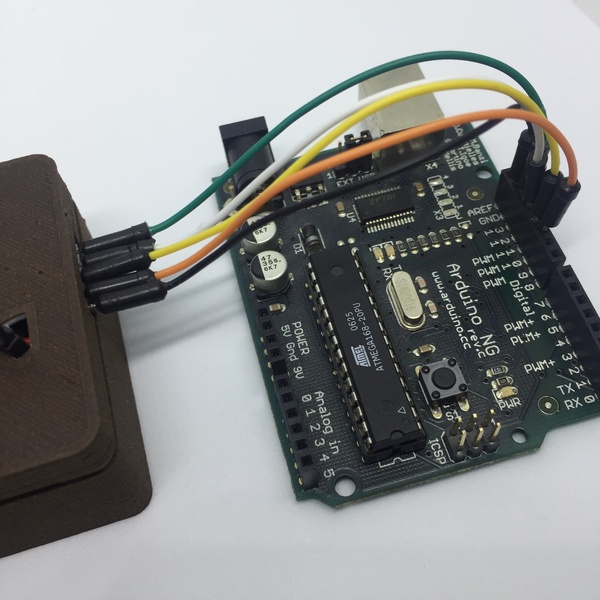
Connecting miniMO to Arduino
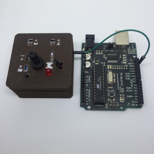
- Place the Arduino so that the longest row of female headers is located at its right

- Place the miniMO to the left of the Arduino, with its female header looking to the right

- Locate the pin marked with the number 13 in the Arduino, and use a jumper wire to connect it with the topmost pin in miniMO

- Connect three more pins one-to-one, going downwards, between miniMO and Arduino (pins 12, 11, and 10). When you finish, the lowermost pin in miniMO won’t have anything connected

- Connect the lower-most pin in miniMO to any pin marked GND in Arduino. I use the pin located over number 13

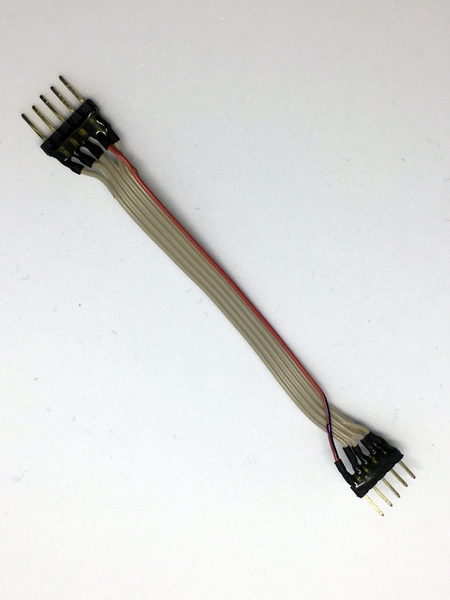
- Unlike with the PCB model, there’s no simple plug-and-play header or connector that I know of. I built a custom connector using a ribbon cable and male headers; you can just glue the bundle of jumpers together in both ends as a quick workaround.


Sending the programs
- Now’s the time to return to the guide on how to program miniMO and follow the steps after Connect

- Hopefully you will get your first program uploaded and running in no time! If it doesn’t happen, don’t despair -check first that you are indeed connecting it correctly to Arduino, then check that all the components are seated properly in the breadboard -especially the microprocessor and the female header-, and make sure the micro is receiving current. If everything fails, you can always remove the ATtiny from the breadboard, connect it to Arduino as shown here, program it, then put it back in place and retest your connections.

Almost Done!
- You should by now have a working oscillator module. Remove the shaft from the base of the potentiometer, place both parts of the case in place, pass the knob shaft through the part named “shaft neck”, and put it back in place.
- If you don’t want to build the case, take a look at the pictures and mark the ports with their numbers, and the positive pins with a dot, so that you know the correct orientation when you connect modules together.

you’re done! congrats!
Pingback: 3d Printed Open Source and Open Hardware Modular Synthesizer | Open Electronics