This is a review of all the versions of miniMO to date, from newest to oldest.
Latest: midiMO
midiMO is the affectionate name I give to a miniMO loaded with a MIDI-related program (like the sequencer), using an adapter that allows it to send MIDI messages to external gear. I released it in late December 2017, and so far it is the latest addition to the ecosystem .
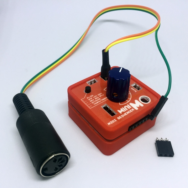
such disruptive ^_^
2017:
- 3D printed-based model (current)
I was happy with the 3D model, but I felt the breadboarded version still had a place in this world, so I took it as a challenge to update it. I redesigned it with the same constraints as the PCB model, fit all the components straight on the board and figured out how to connect everything with no soldering.

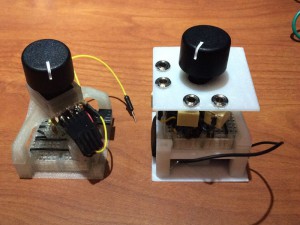
left -miniMO PCB ; right -miniMO Noisette
I called this model the Noisette, and changed from naming it as a breadboarded model to 3D printed model, as was now its more salient feature. I also wrote an extensive guide on how to build and program it, which takes me to the next point,
- Open everything
I started this project as open source; gradually, I’ve moved towards open hardware, publishing files for all parts, accessories, and schematics.
2016: PCB-based model (current)
Come Christmas 2015 I built and took a latte to Toronto, where I demoed it briefly to the nice folks at the Moog Audio store. Everything went well, people liked the design and I got great feedback on the sound and feel. I realized, though, that if I wanted to build more than a handful units and demo them reliably I needed a model that I could build quickly and send by mail not fearing it could break during transit. I set to work on a PCB-based design, and while at it I also decided to see how much I could bring costs down.

Mockup built to get a feel for the unit. The “board” is a paper print straight out from KiCad, cut and glued on thin EVA foam.
The redesign eschews third-party circuits, features a jumper to select from external or battery power, and has identical outputs (previous models filtered them differently). I also designed a number of accessories, from connectors to external cases (see here).
I worked on this unit for most part of the year, and made a minor revision to the circuit in September, based on external feedback and my own experiences with it.

Finished model including minor revisions, like adding the logo
I also designed many 3D- printed parts for this model, including legs, cases and connectors.

Finally, I set this website up and started a Github repository to share all the relevant materials.
2014-15: Breadboard-based models
In late 2013, a series of conversations with my friend Mateo spurred his development of what now are the Hypercubes. I offered to help, but my electronics skills were still very low and all his modules were analog, so I dusted the ATtiny and started to work on a digital module. I thought it would be interesting to show it in addition but also in contrast to the analog modules, both in terms of inner workings and versatility.
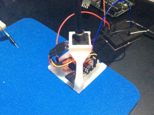
Initially I was trying to follow the hypercube template, so I placed a potentiometer and push button together in an encasing that would fit at the top of the cube.
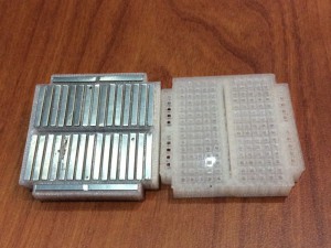
I couldn’t find mini boards with side rails, so I 3D printed custom boards and cannibalized the metal channels from boards I had around.
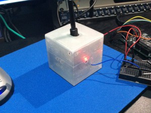
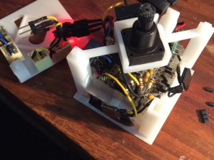
Eventually Mateo and I parted creative ways and I decided to continue working on the digital module. For a while I gave away with the external enclosure and placed the potentiometer+button combo on an arch over the board.
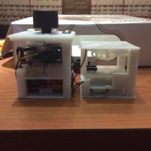
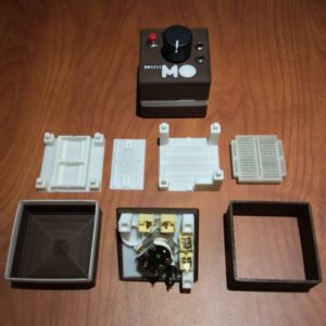
I liked this design, but I wanted it to become portable and easier to connect to other gear. At the time I was running the ATtiny at 16Mhz, so I added a 9-volt battery and a 7805 regulator, eventually replaced by a more efficient model from Pololu. I also added a power switch and mini jacks, and moved the LED, a Neopixel from Adafruit, up; finally, I designed a new enclosure. A friend suggested I could use minimo for the name, so I incorporated it to the design.


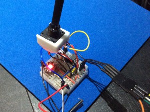
The enclosure comes out easily, and the top components don’t connect directly to the board, so it takes maybe half a minute to disconnect and reconnect them all.
I took this version to a workshop in November-December 2014 in Madrid by Bleeps&Chips and demoed it to friends. The push button proved unreliable, so later on I moved it from its position under the potentiometer to the spot occupied by the power switch. I replaced the potentiometer with a model including an embedded switch to make up for the lost space, and designed a new battery compartment to hold two cr2032 batteries, with a smaller footprint that the 9-volt. I printed the enclosure in the then novelty wood filament from FormFutura, and thought it fitting to call this version the Caffelatte.

I printed all the parts for a couple new lattes, then set on to work in other projects for most of 2015.

2014-15
2009: Early sketches of what was then the LMS, or Little Modular Synth.
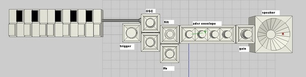
The modules would connect via magnets; distant connections would use cables with magnets at the ends.
I knew almost no electronics at the time, so these sketches remained at the back of my mind until in 2012 a friend suggested I could use an Atmel ATtiny and a DAC to generate tones.