Assembly
1 - Screw the power adapter to the bottom plate
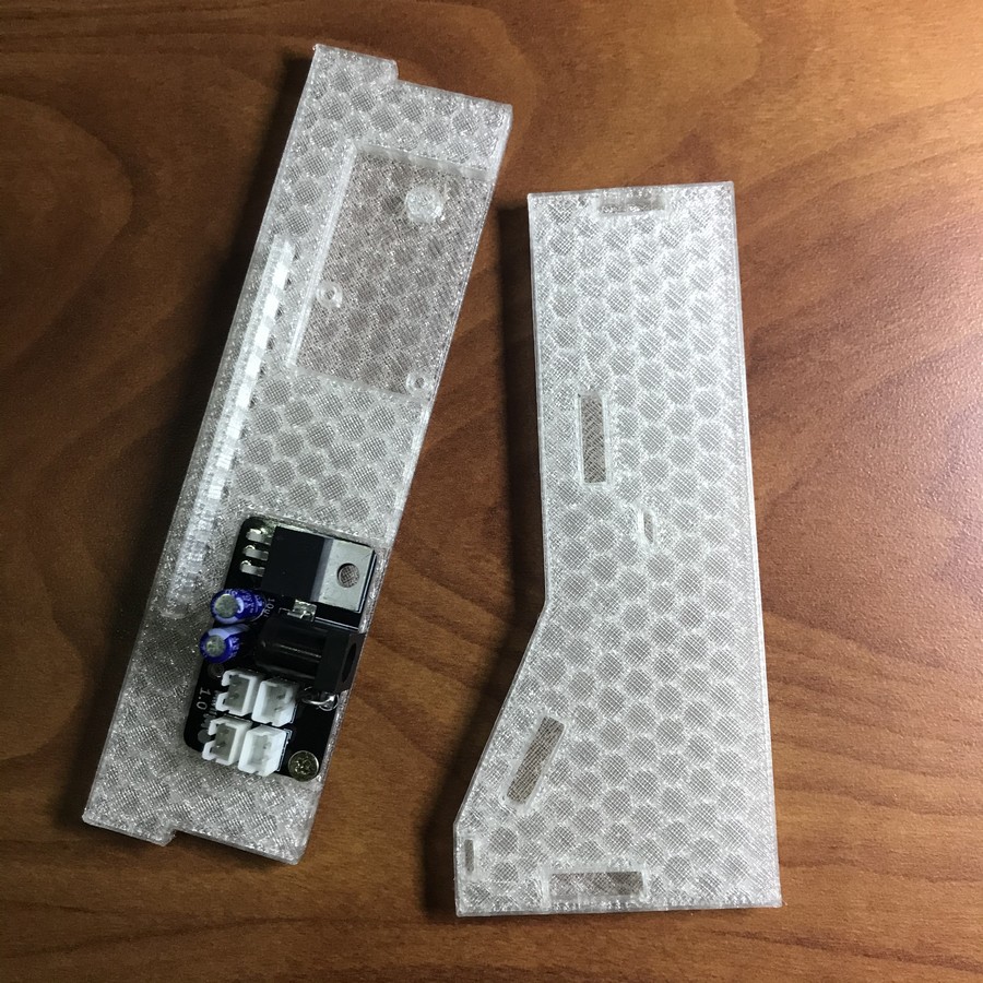
 The bottom plate is different from the rest in that it has spaces to house the power adapter on each side; here, we place it on the left side. Note the orientation, with the barrel jack against the edge of the plate.
This is the only time you'll need to use the screwdriver; the rest of the assembly is snap-on, so you can set it aside now.
The picture below shows the bottom plate with the power source in place, next to the left side plate, which we'll use next.
2 - Snap the bottom plate on to the left side plate

3 - Snap the top plate on to the ensemble
 The upper part is the only rectangular-shaped part of a significant size left at this point. When in place it fits flush against the side plate; if you have trouble orienting it, the "shiny side" points down.
4 - Screw the modules to the frame

The frame is the only part that is not translucent; note the orientation, with the side tabs in the lower half. Proceed one module at a time: pass the module's legs through the holes in the frame, then through the modules, and lock them with the nuts. Also note the orientation of the modules, with the headers pointing up.
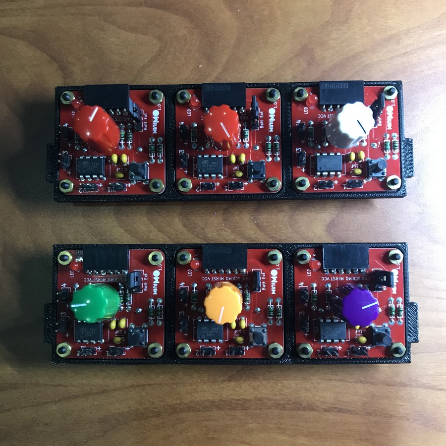 After you have attached the first module, you might want to check again that everything has the right orientation -this is the step that takes the most time, and you definitely don't want to be doing it more than once 🙂
5 - Connect the power rails
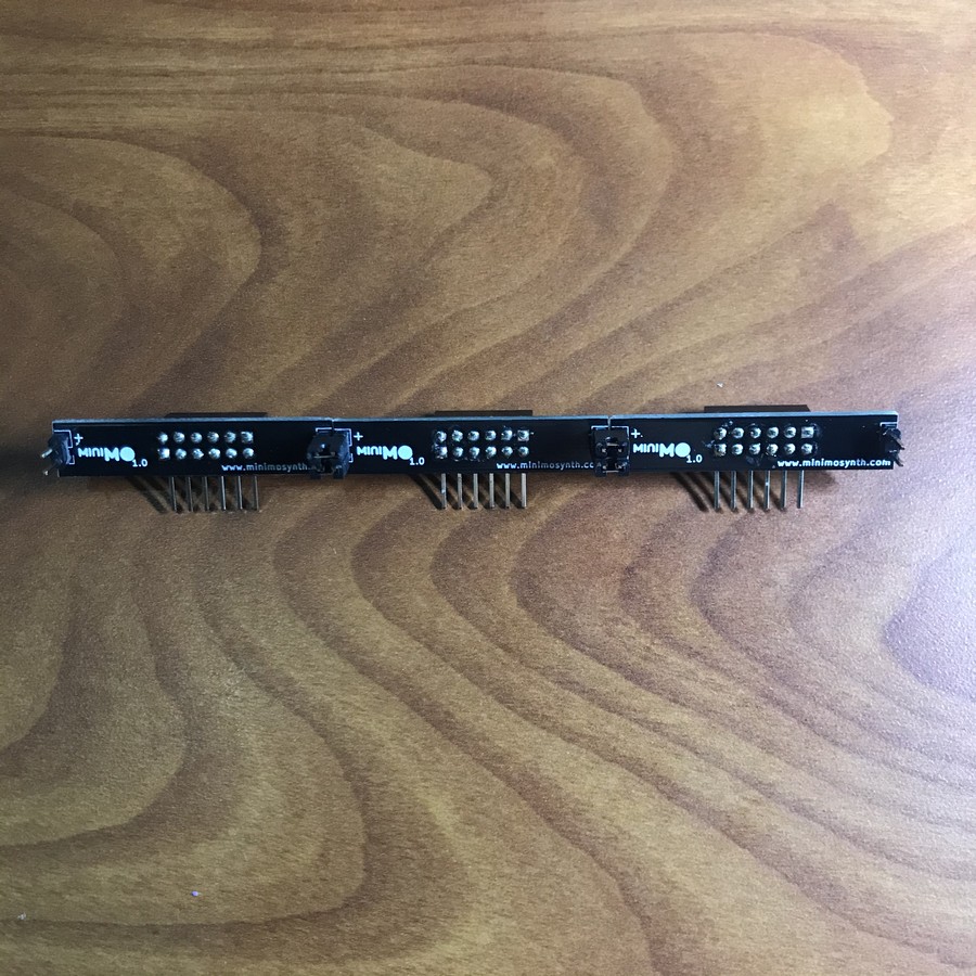 Place the rails side to side like in the picture, and use the jumpers to connect the rail in the middle with those in the sides. Connect + with + and - with -, placing the jumpers sideways.
 In the picture above you can see the jumpers coming out from the left side of a rail; do the same on the other side, then connect the other two rails. In the end you will have free pins on the right and left sides of the groups of three rails.
6 - Attach the rails to the modules
 The rails should fit neatly on the modules, with the central headers all connected.
7 - Snap the front plate on to the case
 Leave the modules aside for a second. Right now you have three parts left -a side plate, and two thin plates, one with indentations, one without. Get the part without indentations and snap it on to the front of the partially completed case. To orient it, see that the rugged side looks outwards, and that the protruding tabs are in the upper half.
This part's tabs are relatively delicate; don't wiggle it from front to back (relative to the rack standing up), or you could break the tab.
 A close look from the part already in place -note the tab in the upper half.
8 - Snap the lower modules on to the case
 Rest the case on its side like in the picture, and slide and snap the lower rack into place.
9 - Snap the back plate on to the case
 The back plate is the long plate with indentations. When you put it in place, the indentations are on the lower half of the part, and the shiny side is on the back. See below how the indentations leave space for the jumpers in the back of the rack.

10 - Snap the upper modules on to the case
 Same as before -slide the upper rack into position.
11 - Attach the right side plate
 This is the hardest step, as you'll have to align and snap all the parts against the remaining plate. Take your time and try to secure the tabs a bit one by one, then gradually press them further. The plates can take a lot of abuse, but avoid wiggling the thin ones back and forth (pressing in, or wiggling up and down, are both OK).
 You're almost done! place the unit standing up, with the back facing you, as in the picture above.
12 - Connect the Power Adapter to the Racks
 Get the cables and snap them on to the sockets in the power adapter -it doesn't matter which, and they fit in the right orientation, so there's no guesswork here.
 Now connect the other end of the cables to the free pins in the side of the rails. Here orientation matters; make sure that the red cable goes to the pin with the + sign (on top). Use the picture above for reference.
13 - Stick the base pads
 This is optional, but the lower surface has a smooth finish, so the pads give extra grip in case you place the unit on a sloped surface.
14 - Set the modules and power the unit ON!
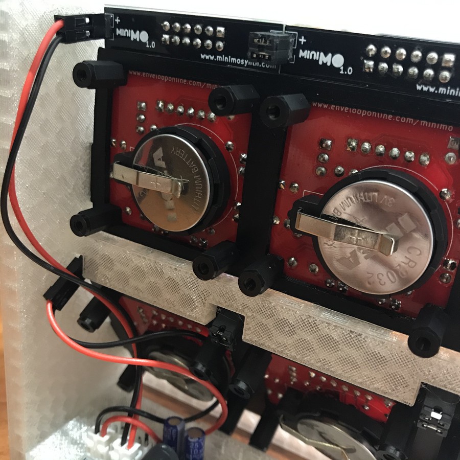
Before you power anything on, place all the modules' power jumpers in the EXT position (two upper pins from the group of three). For as long as you are using the miniRack with external power, you will connect and disconnect the jack at the back to power the unit ON and OFF -the modules always stay in EXT position. Also, to avoid any issues, it's best to use the modules without batteries.

Now connect the power source to the barrel jack, and you should see the modules lighting up!
 If one or two of the modules don't stay lit, like the one in the lower left corner of the picture above, most likely it's because it's not designed to do so -remember, the LED light is not a power indicator necessarily.
If none of the modules light up, then quickly disconnect the power source and recheck the connections in the back. Remember, RED is POSITIVE!
That's it! Note that you can still run the miniRack on batteries, but don't mix power sources -use all external, or all batteries, and remove the batteries from the modules if you're planning to use the miniRack on external power.
Programming
Programming the modules in the miniRack is the same as programming them regularly, but we have to pay attention to the orientations of the miniRack and Arduino to make the pins match. We also want to program the modules in place, so the best solution is to use a cable made with 5 male to male jumper cables with the heads glued together (there's no need to glue them, but it helps). The important things to remember are:
- Connect the cable to the module's header, with the pin labelled GND to the right. The leftmost pin is empty.
- Connect the cable to the arduino aligning that rightmost pin with the GND pin in the strip that reads (top to bottom) GND-13-12-11-10 (etc)
Take a look at the pictures below for reference on how to orient the arduino to make things easier


It is entirely possible to program the modules in the rack using this method if they're running on batteries, and you can even power individual modules from the Arduino using the power pin, but for the sake of a miniRack that's quite unnecessary.
There's nothing particular about programming the modules in the miniRack after this point, so you can now refer to the programming guide to set up the software and load the programs.
That's all! thank you! 😀