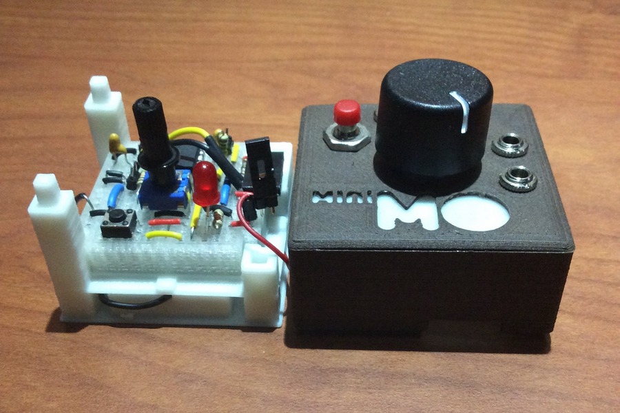
Today I started revising the breadboarded miniMO. I wanted to bring the printed model as much in line as possible with the PCB version, whilst emphasizing the different approach; my goals were to fit all the components of the latest design on the custom board, and to keep soldering to a minimum. In the end, I think I achieved both goals; everything fits and there are only two solder points, both in the programming header (reset and Ground). The picture shows the model assembled on a discarded Mk2’s frame; the battery stays hidden in a lower section.

For the on-off switch I improvised a very simple swiveling mechanism using three male pins and a jumper. I use the leftmost pin as a pivot; since it has a square shape, it locks on 90 degree turns. The jumper acts as a handle, and the center and right pins both rest against a U-bent wire, closing the circuit.

Size-wise, this version is about half as tall as the MkII, and only slightly bigger than the PCB model. Functionally, it is almost the same as the PCB, but it needs cabling to connect it to the Arduino when programming, and it can only draw power from the battery (with the PCB you can either use the battery or an external source).

Now that I have all the internals figured out, it is time to start working on the enclosures; I will be alternating this work with more programming, giving priority to a sequencer.
PS. For contrast, here is a gallery showing a step-by-step gallery of Mk2’s assembly.