I received the PCBs last Friday and built a few MOs over the weekend. I’m very satisfied with how things turned out; the PCBs look sharp, I had no difficulties in soldering the components, and everything works correctly. I found I made a couple of errors with the design, but both have easy fixes and functionality isn’t compromised.
I am particularly pleased with how easy it is to program the miniMO now. I simply attach a 5-pin angled header to the module, place it on the Arduino aligning both ground pins for reference, and that’s it. So far I’ve had no issues whatsoever with programming the units.

Here in the picture you can see the miniMO attached to the Arduino, which in turn is working as an ISP programmer. Arduino is also powering miniMO; I added a switch to the design, so you can select either from the CR2032 battery underneath or from any external source up to 5,5V.
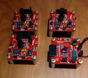
Here, the first four units I assembled. All the units are slightly different from one another, since I am experimenting with different header types, potentiometer caps and switch mechanisms. As it turns out, switches are expensive components (in context), and the only model I found that wouldn’t double the cost of a unit needs a bit of customization to fit the board. I can shave on costs and building time if I use jumpers instead, but the flicking of a switch is a much more satisfactory experience, so I’m divided about this one. Time and feedback will tell!
In all, the new version has met my expectations. Now I can quickly build new units and send them away, which is what I intend to do. 🙂
Following in my list of things to do: well, lots of things, but I think it is time that I post a video or two showing unit operation and sounds.